Komunikasi Serial Arduino
Pink floyd the final cut 2004 torrent. This edition added 'When the Tigers Broke Free' -- originally heard in the soundtrack to The Wall, but its moody, war-obsessed soundscape is better suited for The Final Cut -- as the fourth track, inserted between 'One of the Few' and 'The Hero's Return,' where it fits nicely into the album's narrative.] The Final Cut (Bonus Track) 2004 Pink Floyd.
Now if you open your Arduino serial monitor at a baud rate of 9600, you’ll see a message appearing in your window saying “HI!” every 1 second. Schematics (3.3V FTDI Programmer), follow the next schematics to establish a serial communication between your FTDI programmer and your ESP8266 to upload some code.
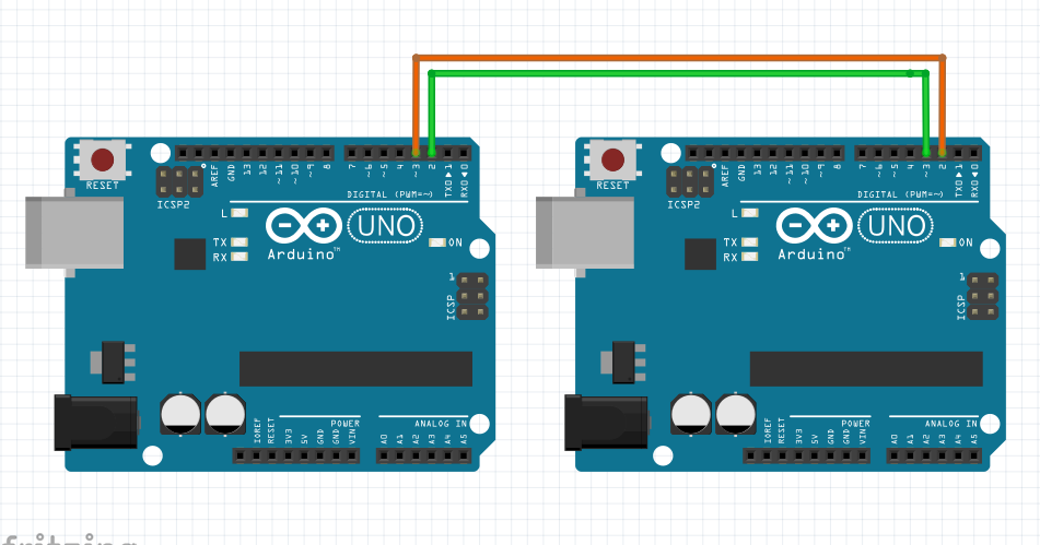
Farhan ali qadri naat mp3. Arduino (dalam proyek ini saya menggunakan arduino nano). 5 buah led untuk indicator komunikasi serial ke arduino; kabel jumper secukupnya. Pada dasarnya komunikasi serial I2C telah kita aplikasikan penggunaannya pada blog ini yaitu komunikasi antara Arduino Microcontroller dengan modul clock DS1307. Dasar Komunikasi Serial dari Arduino Kemampuan untuk bisa melakukan komunikasi data antara 2 atau lebih peralatan elektronik adalah hal yang sangat penting yang harus dimiliki oleh sebuah microcontroller. Dan yang lebih penting lagi, kemampuan komunikasi tersebut tidak boleh sampai mengurangi fungsi dari microcontroller itu sendiri.
Downloading ESPlorer IDE I recommend using the ESPlorer IDE which is a program created by 4refr0nt to create and save Lua files into your ESP8266. Follow these instructions to download and install ESPlorer: • to download ESPlorer • Unzip that folder • Go to the main folder • Run ESPlorer.jar • Open the ESPlorer (as shown in the Figure below). Writing Your ESP8266 Script Copy and paste the code below into ESPlorer IDE window. -- Rui Santos -- Complete project details at ledOn = 0 pin=4 gpio.mode(pin,gpio.OUTPUT) uart.on('data', 3, function(data) print('Received from Arduino:', data) if data=='HI!' Then if ledOn==0 then ledOn = 1 gpio.write(pin,gpio.HIGH) print('LED On') else ledOn = 0 gpio.write(pin,gpio.LOW) print('LED Off') end end end, 0). Summary: The ESP is configured to listen to serial communications. Every time that receives the string “HI!” at a baud rate of 9600, it will turn the GPIO 2 on or off.
Uploading Your Script When you open the ESPlorer IDE you should see a window similar to the preceding Figure, follow these instructions to send commands to your ESP8266: • Connect your FTDI programmer to your computer • Set bad raute as 9600 • Select your FTDI programmer port (COM3, for example) • Press Open/Close • Select NodeMCU+MicroPtyhon tab • Copy the your Lua script into ESPlorer Then you simply click the button Save to ESP and save your file with the name “init.lua”. Everything that you need to worry about or change is highlighted in red box in the following Figure. Final Circuit Follow the next schematics to complete this tutorial. Note: I’m using a voltage divider to shift the TX signal of the Arduino from 5V to 3.3V. This works well for slow baud rates, but it might not work at faster baud rates.
For more information about lowering the voltage of signals. Demonstration Now your LED should be blinking every one second. This means that your Arduino is sending the string “HI” and your ESP is receiving that data. Watch the video at the beginning of this post for a live demonstration.
Now instead of sending a string saying just “HI!”, you can attach sensors to your Arduino and send that data to your ESP instead. Later you can that displays that data. Read Next You might also find interesting trying one of these tutorials: • • • Do you have any questions? Leave a comment down below!
Thanks for reading. If you like this post probably you might like my next ones, so please support me by subscribing my.